For most unmanned aircraft systems, propulsion and flight control perform different tasks. The propulsion system creates a longitudinal force, and the change in orientation of the vehicle is provided by aerodynamic surfaces - ailerons, elevators, rudders, or a combination thereof.
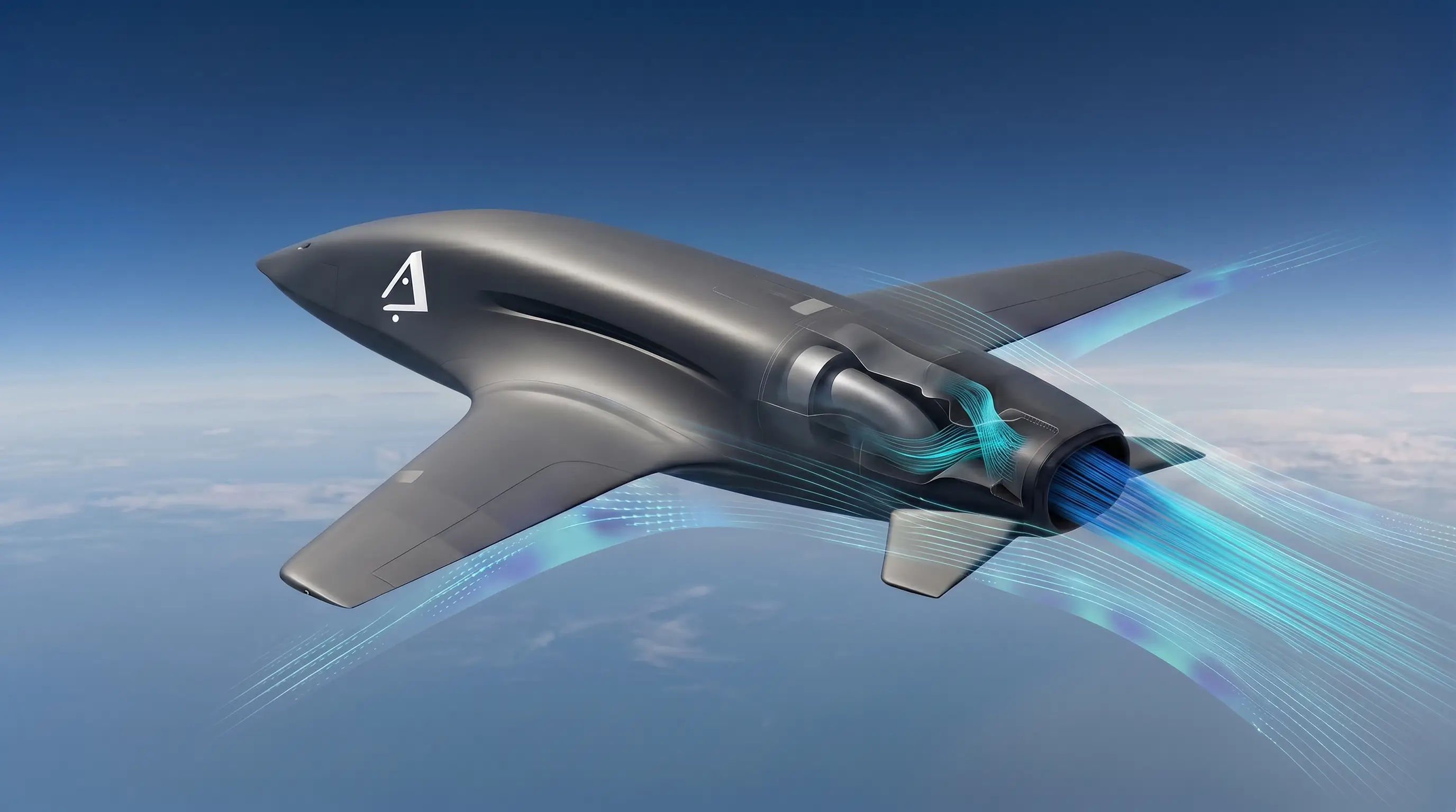
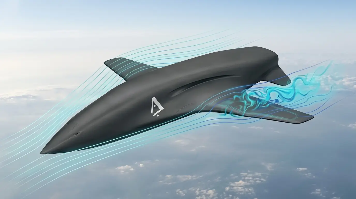
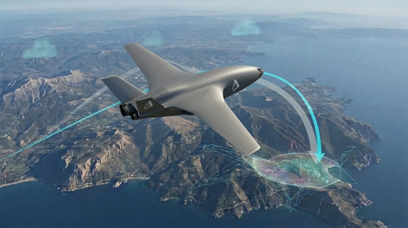
AERIS VectorFlow explores a different architecture: the direction of the jet stream becomes an additional controllable parameter, and the propulsion system itself becomes part of the propulsion control loop. In this case, the task is not to install a separate external vector module, but to integrate flow control into the geometry of the device.
From a constant thrust vector to a controlled one
In a conventional configuration, the direction of thrust is almost constant relative to the body. To change pitch, yaw, or roll, the aircraft must generate additional aerodynamic torque using a control surface.
When vectoring thrust, part of this moment can be generated directly by the power plant. By changing the direction of the outgoing flow relative to the longitudinal axis of the device, the system gains an additional way to control its spatial movement.
- longitudinal thrust is used to create forward motion;
- deviation of its direction creates additional control torque;
- the thrust vector can work in conjunction with aerodynamic surfaces;
- The relationship between aerodynamic and reaction control can change depending on the flight mode.
As a result, the propulsion system ceases to be only a source of acceleration and begins to participate in the formation of the dynamics of the apparatus.
Why VectorFlow is integrated into the design
One of the key principles of the project is to minimize external elements that impair the aerodynamic shape of the vehicle. Therefore, VectorFlow is not considered as an additional device installed behind the engine, but as a functional part of the aft area and internal air path.
This approach is especially important for compact UAVs, where the mass, drag and footprint of any individual mechanism significantly affect the performance of the entire platform.
Integration allows the motor, flow path, outlet housing and control system to be treated as a single task rather than as several components connected in series.
Control when aerodynamic surfaces lose effectiveness
The capabilities of classic control surfaces directly depend on the air flow. When the speed, angle of attack and local flow state change, the forces and moments they create also change.
Thrust vectorization uses a different physical mechanism. The control action is formed by changing the flow impulse of the power plant and therefore can complement aerodynamic control in modes where the effectiveness of individual surfaces becomes limited.
For an unmanned vehicle, this creates the opportunity to distribute the control action between several mechanisms instead of completely depending on one method of creating torque.
Control allocation
The presence of several control methods does not in itself make the device more efficient. The main task is to determine which actuator should be used at a particular moment.
The thrust vector can be useful in one mode and energetically disadvantageous in another. Therefore, VectorFlow is considered together with the control action distribution algorithm.
- in stable flight, priority may remain with the most efficient aerodynamic control method;
- during a fast maneuver, part of the required torque can be generated by changing the direction of thrust;
- if the effectiveness of one of the control surfaces is limited, the system receives an additional channel of influence;
- the algorithm must take into account available thrust and propulsion limitations.
Thus, the task of VectorFlow is not to constantly use vectorization, but to include it in the overall control system, taking into account the current mode.
Coupling propulsion and aircraft dynamics
With a fixed direction of thrust, a change in engine power is primarily considered as a change in longitudinal force. In a system with a controlled vector, the situation becomes more complicated: the magnitude of the thrust simultaneously determines the potential magnitude of the control torque created.
This means that propulsion and spatial motion control cannot be considered independently. Changing engine mode affects the available range of reactive control, and flow deflection can affect the effective longitudinal component of thrust.
VectorFlow therefore requires coordinated operation of the motor and control circuits.
Thrust loss as part of the task
The deflection of the jet stream does not create a control torque for free. The more the direction of flow differs from the optimal longitudinal direction, the smaller part of the total thrust is used directly to accelerate the apparatus.
Additional losses may also occur within the air path. A change in the direction of a high-speed flow is accompanied by velocity heterogeneity, local resistance and other effects that must be taken into account during design.
Therefore, the effectiveness of VectorFlow is determined not by the maximum possible deflection angle, but by the relationship between the generated control torque and thrust losses.
Why is the internal air path important?
For an integrated powertrain, the characteristics are determined not only by the engine itself. The inlet channel, the engine area, the output path and the geometry of the aft part work as a single gas-dynamic system.
If flow direction control is added to this system, its effect on the distribution of velocities and pressures within the path must be considered.
- the flow must maintain sufficient homogeneity in front of the control region;
- changing the direction of the jet should not create excessive internal losses;
- the geometry of the output path must take into account several operating modes;
- the control action must remain reproducible throughout the entire thrust range under study.
This is why VectorFlow is viewed as an integration problem between aerodynamics, propulsion and control, rather than as a separate actuator.
Experimental verification
The calculation allows a preliminary assessment of the direction of flow and the forces generated, however, for compact integrated installations, experimental verification is especially important.
It is necessary to determine the actual relationship between the control command, the engine mode, the direction of the outgoing flow and the torque that the aircraft receives.
The transition process is of particular interest. For the control system, not only the established thrust vector is important, but also how quickly and predictably the required impact is generated.
- measurement of actual loss of longitudinal thrust;
- assessment of created control moments;
- study of transition regimes;
- checking the repeatability of the control action;
- comparison of the calculated model with the results of a real flight.
Limitations and engineering risks
Integrated vectorization increases the mutual influence of subsystems. Changing one part of the air path can simultaneously affect thrust, control efficiency and thermal conditions.
In addition, the system must maintain predictable behavior when available power is limited or the flow direction control mechanism fails. Therefore, the basic aerodynamic stability of the vehicle remains an important condition for the experimental architecture.
- flow deviation leads to the loss of part of the longitudinal thrust;
- non-uniform flow can reduce the reproducibility of the control torque;
- the available control input depends on the current engine mode;
- the internal mechanism must operate under conditions of vibration and high-speed flow;
- The control algorithm must take into account the physical limitations of the power plant.
The AERIS approach
AERIS VectorFlow is exploring the possibility of making the propulsion system a functional part of the control of the unmanned vehicle, while maintaining the clean external geometry of the platform.
The main interest is not the maximum deflection of the jet in itself, but the coordinated work of aerodynamics, thrust and the control action distribution algorithm.
This approach allows us to consider flight control as a problem of using several available physical mechanisms, each of which can have advantages in a certain region of the regime.
VectorFlow is at the research and experimental testing stage. The goal of the program is to identify modes in which integrated thrust vectoring provides a measurable advantage, and to determine the cost of this advantage in thrust loss, weight, complexity and power consumption.